MikroElektronika

Tested Environment:
| CPU |
IDE |
OS |
Ethernet |
RS-232 |
RS-485 |
|---|---|---|---|---|---|
| MikroEletronika PIC18F45K22 |
MikroC |
N/A |
Yes |
Yes | Yes |
Characteristics:
| CPU | Read Coils | Read Discrete Inputs |
Read Coils + Write Coils |
Read Input Registers |
Read Holding Registers |
Read Holding registers + Write Holding Registers |
All 8 Functions |
|---|---|---|---|---|---|---|---|
| MikroEletronika EasyPICv7 |
3 | 3 | 3 | 3 | 3 | 3 | 3 |
Verify the code before buying
RTips Technologies provides a hex file so that the customer can test the code before buying the library
Modbus Slave RTU - Hex file download
After downloading the hex file make sure you follow the steps for proper communication
- For testing the Modbus Slave use Modbus Master (Eg: download Wintech Modscan32 http://www.win-tech.com/html/modscan32.htm which is available free or you can use any Modbus Master which you are familiar). The below steps are written
by taking Modscan as reference however configurations remains same for any Modbus Master.
- Load and write the hex file into the MikroProg Suite for PIC
- For RTU: Open Modscan, go to Connection->Connect a dialog box appears where you need to set the following configuration.
- Baud Rate: 9600
- Word Length: 8
- Parity: None
- Stop Bits: 1 as shown below
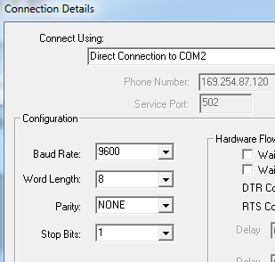
- Baud Rate: 9600
- After connecting, set Address: 0001 Length: 10 ( As we are sending 10 dummy data values from the Modbus Slave, anything beyond 10 shows 'Exception Response') Device Id: 1
- Now the Modbus master will be ready to communicate with the Slave.

Porting Example:
- Modbus application that reads a potentiometer on the board and transmits its value in "16-bit integer". This will demonstrate how an application can pass on data (the pot reading in this case) to the Modbus library. The value of the pot is the tied into a holding register of Modbus and sent back to the master
- Step1: Set the Jumpers and include necessary library(ADC) to turn on Potentiometer.
- Step2: Make all the declarations of Potentiometer in "Modbus.c"
- Step3: Get the Potentiometric value and tie with the "Holding Register"
- Below shows the code snippet
- "MSPL_UserIf.c"
- CSPL_U8 MSPL_ReadUserData(CSPL_U8 slaveID, CSPL_U8 networkNo, CSPL_U8 functionCode, CSPL_U16 startAddress, CSPL_U16 noOfItems, CSPL_U8 *pBuffer) {
- adc_rd = ADC_Read(1);
- switch(functionCode) {
- -----------
- -----------
- case FC_READ_HOLD_REGS:
- HoldingReg[0]= adc_rd ;
- -----------
- -----------
- Below shows the code snippet
- Step1: Set the Jumpers and include necessary library(ADC) to turn on Potentiometer.
- Modbus application where the master write 1 to coil address 0 and a declared variable value turn from 0 to 1 in order to trigger an event.
- The example demonstrates Led On/Off of 'PORTA'. In the function 'CSPL_U8 MSPL_WriteUserData()' (present in 'MSPL_UserIf.c') When the Coil is set to '1' you can see the Led's of PortA are ON and vice versa. Below Shows the code
Snippet
- "MSPL_UserIf.c"
- CSPL_U8 MSPL_WriteUserData(CSPL_U8 slaveID, CSPL_U8 networkNo, CSPL_U8 functionCode, CSPL_U16 startAddress, CSPL_U16 noOfItems, CSPL_U8 *pBuffer) {
- switch(functionCode) {
- -----------
- -----------
- case FC_WRITE_SINGLE_COIL:
- if(Coil[0]==1)
- LATA=0x00
- if(Coil[0]==0)
- LATA=0xFF
- -----------
- -----------
- "MSPL_UserIf.c"
- The example demonstrates Led On/Off of 'PORTA'. In the function 'CSPL_U8 MSPL_WriteUserData()' (present in 'MSPL_UserIf.c') When the Coil is set to '1' you can see the Led's of PortA are ON and vice versa. Below Shows the code
Snippet